
Home... Help... Search... Bikes...
My Box-Trike building page
My page on cargo-trikes gives some background to this building project. I'll expand this as it progresses, but for now some early pictures and notes:-
Well, yes. Retirement and all sorts of family demands (including delightful twin grandkids) have taken their toll. However, the workshop revamp is almost finished and things are moving again.
The next step is to join the front and back halves of the frame, ie, marrying up the square-tube boom with the cut-off rear part of an junk mountain bike that was given to me. As I don't weld, and haven't the gear, and the bike frame is aluminium, it will be held together with steel plates and bolts.
The wheelbase (ie, distance from the front axle line to the rear axle) is 1270mm (50") the same as the Haley Trikes from the specs on. A mock-up showed the boom needed to be shortened (as expected - I allowed a fair bit of extra length when I made the boom last year - remember, there are no drawings for this project, just ideas and "try-it-and-see").
Here is my young assistant cutting the boom to length using an angle grinder in a drop-saw frame ($20 from SuperCheap Auto). The frame is die-cast, and the workpiece clamp was not very good, being flimsy and getting in the way of the grinder head, so I mounted the base to a piece of 16mm MDF board and made a workpiece fence from a piece of pine. We use clamps to hold the workpiece in place. Note the faceshield and safety glasses! The first lesson is always safety. We set the workpiece up together, and I did the first cut (the grinder is a 100mm Ozito cheapie, with a 1.6mm thick metal cutting disk, and we cut the tube in 4 steps).

We marked the boom for the holes for the bolts that will fasten the steel plates. Here the drilling is being done. Assistant used a drill of about 3mm to make pilot holes, then drilled 8mm all the way through. {{Note: the new drill press is great! A Carbatec floor mounted column drill, 16mm chuck, and 550 watts (3/4 HP). This was my retirement present from my employer; only took me a year to get it installed!}}

The ball cages in the old bottom bracket/pivot were cracked, so a new set was needed. First bike shop did not have any, and the second had a complete kit (cups, cones, bearings, washers, nut) for $12.95. Very quick work to install them - the old cups had some corrosion too, so I'm more than happy with the fully greased and slick new set.


You can see that I've replaced the 1/4" bolts holding the old bottom bracket to the square tube with 3/8" bolts. This seems to be very rigid now. Note the 1/2" bolts for the steering angle pivot and adjuster - I do not want any slop or flexing here.

Despite the hefty appearance, the whole rig including the main boom is only about 4.5Kg (10 pounds).
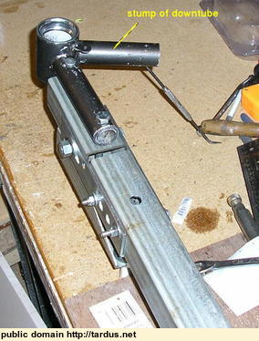
Here you can see the stump of the bottom bracket's seat tube. If the bolted connection proves as rigid as I hope the stump can be cut off. Otherwise I'll cobble up some sort of lateral connection from it to the the boom, to give greater torsional stiffness. It was still a must to permit accurate drilling of the bolt holes through the main tube of the bottom bracket. Being the same overall diameter as the main tube, the seat tube made the unit self-aligning on my drill press table.

BTW - if you wonder about the mixture of metric and inch size bolts, while here in Australia we went metric back in the 1970s, the typical stuff you find at the local hardware is still inch sizes. Metric sizes are finally getting to be common (you could always get then from engineering supply places, but not the local). So, its a matter of what I can find at the time!
BTW2 - one of the most useful tools so far has been my Chinese drill-press ($99 a few years ago). The ability to drill accurate holes in metal at low speed, at right angles, and with minimal effort, is such a simplifying thing. I doubt I could have drilled the holes in the pivot assembly and square tube accurately enough by hand. As it is now, the two pieces are square with each other and the bolted joint is nice and rigid.
Here is the front frame on its wheels


25th Feb 2010

A simple sketch of the rear of a mountain bike with the box front

I don't have welding skills, so the frame is made of thin steel channels used for house framing. These are 64mm x 34mm, and the studs nest with the channels closely. When pop-rivetted the box section becomes torsionally stiff.

Wood stiffeners are inserted in the middle of the centre channels. This is where the pivot will attach, and needs to be rigid. The wood is glued in place with "Maxbond", a cheap and tough gap-filling construction cement (a "Liquid Nails" type product, but better at gap filling and bonding almost anything to almost anything else).

The centre channels are doubled and rivetted

Here the centre channels are rivetted in place to the front and rear channels

Here's what it looks like with a wheel in place (just mocked up, not fixed in place yet)

The channels that support the front wheels need some reinforcements. The steel is only 0.5mm thick; strong but not rigid. Here are the four aluminium pads, from 3mm material

A pad rivetted in place

The pivot will be the bottom bracket from a junk BMX bike. Here is the crank approximately in place, just to get an idea.

Here is the donor BMX and the bottom bracket cut from it

To make the bottom bracket assembly self-aligning the cut-off main and seat tubes need to have the same diameter. Fortunately the off-cuts of the main tube along with a bit of other bike tube I had nest closely over the seat tube stub. I've put off-cuts inside the main tube as well, so it has plenty of crush-resistance when it is through-bolted to the trike's main tube

The nested tubes ready to be pressed home

And in place

The pivot assembly from the top

And the side

Home... Help... Search... Bikes...
This page tardus.net/boxTrike.html Last refreshed: 04 Oct 2023
Contact me, "Tardus"
Copyright
 powered by txt2tags
